Playing with the Pico Part 6 - SNES like sprites and tilemap with VGA

In Part 5 we produced a simple video test pattern, how about something more interesting, like this?

A monitor attached to a pico displaying some character sprites over a tile map

Full code can be found on github

This is the final result of the code discussed below, so how does it all work?

It would be straight-forward to display a static image or framebuffer. With the 320x240 resolution and 2 bytes per pixel that’s 150 KiB which we can fit in the Pico’s memory. The problem is we can only fit one frame’s worth of image in memory, what if we want a changing image, e.g. some kind of game?

Say we did want to write a game, we could just use a single frame buffer, the problem is if we update the buffer whilst it’s being displayed you end up seeing a mix of the old and new frames. You can avoid this by only updating the buffer when you’re in the vertical blanking interval but this gives you limited time to draw your frame. If you’re careful you can ‘chase the beam’ where you update the frame buffer as it’s being drawn but carefully only change a particular pixel once it’s been output. This gives you more total frame draw time but will be more awkward to get right.

Even with careful programming to allow use of a single buffer without visual artifacts you’re still using a lot of memory. Plus using 150 KiB of 264 KiB memory total just for the framebuffer you’ll have limited memory available for everything you need to draw the frame.

We’re going to choose another tactic, drawing the frame one scanline at a time. Whilst we’re outputting one scanline we’ll draw the next one. This is the ‘chasing the beam’ technique but avoiding a full frame buffer. We will have two line buffers, one for the line we’re currently outputting and one of the line we’re currently drawing.

Let’s make some alterations to the code from the previous blog to support this. We already had two separate line buffers one for a white line and the other for a red, green, blue, black pattern. We’ll switch this to two generic buffers using one for the even lines (0, 2, 4 etc) and the other for the odd lines (1, 3, 5 etc). Whilst one buffer is being streamed out by DMA the other will be filled by software. This can be done with the following code in the interrupt handler:

1
2
3
4
5
if (current_display_line & 2) {
    dma_channel_set_read_addr(line_dma_chan, line_data_buffer_odd, true);
} else {
    dma_channel_set_read_addr(line_dma_chan, line_data_buffer_even, true);
}

There’s a subtlety here as we’re outputting 320x240 graphics at a 640x480 resolution. So every line gets repeated twice. This is what the current_display_line & 2 accomplishes. Display lines 0 and 1 (current_display_line & 2 == 0) both output the first even line. Display lines 2 and 3 (current_display_line & 2 == 1) both output the first odd line.

How do we coordinate this with whatever software is filling the line buffers? We don’t want to do that in the interrupt handler as generally they should be kept as short as possible (because they block other interrupts from occurring). I’ll use a very simple polling loop. It’ll use a boolean flag new_line_needed. The polling loop will wait for the interrupt handler to set new_line_needed and start filling the appropriate buffer when it is set. A separate next_line variable will hold which (320x240) line needs to be drawn next. We’ll call a function draw_line(int line_y, uint16_t* line) which will draw whatever should be at the line line_y position on the screen into the buffer line.

Here’s the polling loop:

 1
 2
 3
 4
 5
 6
 7
 8
 9
10
11
12
13
14
15
16
17
18
19
20
21
22
23
24
25
26
27
28
while(1) {
    // Wait for an interrupt to occur
    __wfi();

    // Temporarily disable interrupts to avoid race conditions around
    // `new_line_needed` being written
    uint32_t interrupt_status = save_and_disable_interrupts();

    // Check if a new line is needed, if so clear the flag (so the loop doesn't
    // immediately try to draw it again)
    bool do_draw_line = new_line_needed;
    if (new_line_needed) {
        new_line_needed = false;
    }

    // Reenable interrupts
    restore_interrupts(interrupt_status);

    // If a new line is required call `draw_line` to fill the relevant line
    // buffer
    if (do_draw_line) {
        if (next_line & 1) {
            draw_line(next_line, line_data_buffer_odd);
        } else {
            draw_line(next_line, line_data_buffer_even);
        }
    }
}

Here’s the code from the interrupt handler that sets new_line_needed and next_line:

1
2
3
4
5
6
7
8
9
// Need a new line every two display lines
if ((current_display_line & 1) == 0) {
    // At display lines 478 & 479 we're drawing the final line so don't need
    // to request a new line
    if (current_display_line < 478) {
        new_line_needed = true;
        next_line = (current_display_line / 2) + 1;
    }
}

We’re not quite done yet, we need to think a little more about the beginning of the frame. The interrupt that’s setting new_line_needed is doing it when the line DMA channel is done sending buffer data. This is fine in the middle of the frame but for the first 2 display lines of the frame there’s no previous display lines to trigger the interrupt to kick off draw_line for line 0. An easy way to handle this is with some dummy lines. We’ll start outputting visible lines before the display region, just streaming out 0 pixels. This won’t alter the output on the pins but will give us the DMA interrupt with the exact same timing we get during the visible lines.

We’ll output 3 dummy lines, by adding some visible lines to the beginning of the command words we send to the sync PIO. At the end of the first dummy line we’ll signal new_line_needed setting next_line to 0. Giving the software the same time to draw the first line that it gets for all other lines (the time taken to output a line twice).

To save a little bit of memory we’ll set the line DMA not to increment its read address for the zero lines, so we’ll point it at a 32-bit memory location containing a zero which it will read over and over. This requires a little extra code to alter the line DMA config between the dummy lines and the real display lines. Here’s the final code for the interrupt handler:

 1
 2
 3
 4
 5
 6
 7
 8
 9
10
11
12
13
14
15
16
17
18
19
20
21
22
23
24
25
26
27
28
29
30
31
32
33
34
35
36
37
38
39
40
41
42
43
44
if (current_display_line == 479) {
    // Final line of this frame has completed so signal new frame and setup for next.
    new_frame = true;

    // 3 dummy lines before real lines
    current_display_line = -3;

    // Setup Line DMA channel to read zero lines for dummy lines and set it going.
    // Disable read increment so just read zero over and over for dummy lines.
    // DMA won't actually begin until line PIO starts consuming it in the next
    // frame.
    channel_config_set_read_increment(&line_dma_chan_config, false);
    dma_channel_set_config(line_dma_chan, &line_dma_chan_config, false);
    dma_channel_set_read_addr(line_dma_chan, &line_data_zero_buffer, true);
    return;
}

current_display_line++;

// Need a new line every two display lines
if ((current_display_line & 1) == 0) {
    // At display lines 478 & 479 we're drawing the final line so don't need
    // to request a new line
    if (current_display_line != 478) {
        new_line_needed = true;
        next_line = (current_display_line / 2) + 1;
    }
}

if (current_display_line == 0) {
    // Beginning visible lines, turn on read increment for line DMA
    channel_config_set_read_increment(&line_dma_chan_config, true);
    dma_channel_set_config(line_dma_chan, &line_dma_chan_config, false);
}

// Negative lines are dummy lines so output from zero buffer, otherwise
// choose even or odd line depending upon current display line
if (current_display_line < 0) {
    dma_channel_set_read_addr(line_dma_chan, &line_data_zero_buffer, true);
} else if (current_display_line & 2) {
    dma_channel_set_read_addr(line_dma_chan, line_data_buffer_odd, true);
} else {
    dma_channel_set_read_addr(line_dma_chan, line_data_buffer_even, true);
}

This adds a new_frame flag we can use in our polling loop:

 1
 2
 3
 4
 5
 6
 7
 8
 9
10
11
12
13
14
15
16
17
18
19
20
21
22
23
24
25
26
27
28
29
30
31
32
33
34
35
36
37
38
39
while(1) {
    // Wait for an interrupt to occur
    __wfi();

    // Temporarily disable interrupts to avoid race conditions around
    // `new_line_needed` being written
    uint32_t interrupt_status = save_and_disable_interrupts();

    // Check if a new line is needed, if so clear the flag (so the loop doesn't immediately try
    // to draw it again)
    bool do_draw_line = new_line_needed;
    if (new_line_needed) {
        new_line_needed = false;
    }

    // Check if a new frame is needed, if so clean the flag (so the loop doesn't immediately
    // signal a new frame again)
    bool do_end_of_frame = new_frame;
    if (new_frame) {
        new_frame = false;
    }

    // Reenable interrupts
    restore_interrupts(interrupt_status);

    // If a new line is required call `draw_line` to fill the relevant line
    // buffer
    if (do_draw_line) {
        if (next_line & 1) {
            draw_line(next_line, line_data_buffer_odd);
        } else {
            draw_line(next_line, line_data_buffer_even);
        }
    }

    if (do_end_of_frame) {
        end_of_frame();
    }
}

We’ll write a draw_line and end_of_frame to produce another test pattern, one that changes line by line and frame by frame. It has a 1 pixel white border like the previous one and produces alternating bars of red, green and blue with a colour gradient in each going from black to full red, green or blue. Every frame we adjust the start point of this gradient. Here’s the code:

 1
 2
 3
 4
 5
 6
 7
 8
 9
10
11
12
13
14
15
16
17
18
19
20
21
22
23
24
25
26
27
28
29
30
31
32
33
34
35
36
37
38
39
40
41
42
43
44
45
46
47
48
49
50
51
52
53
int start_colour_val = 0;
bool start_colour_val_inc = true;

void draw_line(int line_y, uint16_t* line) {
    if ((line_y == 0) || (line_y == 239)) {
        // Top and bottom lines are white
        for (int i = 0;i < 320; ++i) {
            line[i] = 0xffff;
        }

        return;
    }

    // Each colour area is 32 pixels high and rotate around red, green and blue. Determine whether
    // we're in a red, green or blue colour area (colour_area == 0, 1 or 2).
    int colour_area = (line_y / 32) % 3;
    // Within the colour area where are we in the gradient
    int colour_val = (line_y + start_colour_val) % 32;

    // Produce R, G, B values given the colour_area and colour_val
    int r, g, b;
    if (colour_area == 0) {
        r = colour_val;g = 0; b = 0;
    } else if (colour_area == 1) {
        r = 0;g = colour_val; b = 0;
    } else if (colour_area == 2) {
        r = 0;g = 0; b = colour_val;
    }

    // Fill line with calculated R, G, B values
    for (int i = 0; i < 320; ++i) {
        line[i] = ENCODE_RGB(r, g, b);
    }

    // Set first and last pixels to white for the border
    line[0] = 0xffff;
    line[319] = 0xffff;
}

void end_of_frame() {
    // Every frame increment or decrement start_colour_val
    if (start_colour_val_inc) {
        start_colour_val++;
    } else {
        start_colour_val--;
    }

    if (start_colour_val == 0) {
        start_colour_val_inc = true;
    } else if (start_colour_val == 31) {
        start_colour_val_inc = false;
    }
}

Finally, an important point. new_line_needed, new_frame and next_line need to be declared volatile, like this:

1
2
3
volatile bool new_frame;
volatile bool new_line_needed;
volatile int next_line;

This tells the compiler the value might change unexpectedly so it has to read or write the actual memory holding the variable every time rather than optimising (either leaving it in a register or just realising the variable must be some fixed value at a particular point in the code so not even checking it). Look at this simplified version of our polling loop to see what happens without volatile:

1
2
3
4
5
while (1) {
  if (new_line_needed) {
    draw_line(next_line, line_data_buffer);
  }
}

If new_line_needed is false at the start of this loop the compiler could just optimise it to an infinite loop that does nothing. However we know an interrupt will eventually set new_line_needed to true. By using a volatile variable for new_line_needed the compiler won’t do this optimisation and instead loop checking the memory that holds new_line_needed each time.

Here’s a video of the test pattern in action:

At the beginning I promised something more interesting and we’ve just produced yet another test pattern but we now have everything we need to move on to drawing complex frames. First up let’s look at sprites.

A sprite is just an image you draw on the display. You provide the sprite image data, a width and height, an X and Y position and let the graphics library or graphics hardware do the rest. They were a major feature of earlier 8-bit and 16-bit consoles (like the NES, SNES and Megadrive) as well as some 80s and early 90s home computers (like the Commodore 64 and Amiga). The hardware of these machines had native sprite support, allowing you to draw complex frames without needing enough memory for a full frame buffer.

Here’s an example set of sprites for a character with a few basic animations (Art by Charles Gabriel). The image size has been increased so it doesn’t look too tiny on modern monitor resolutions.

A sprite sheet containing multiple animation frames for a single character

Generally sprites can have transparent pixels, allowing you to draw complex objects over a background and this implementation will be no exception. Any bright pink (R = 31, G = 0, B = 31) pixels in a sprite will be transparent.

Given a list of sprites we can determine which are on the scanline we are currently drawing, these are the active sprites for that scanline. After determining the active sprites we just copy the non-transparent pixels from the relevant line of sprite data from each out to the scanline. Overlapping sprites are dealt with using the order of the list. A sprite that appears earlier in the list will be drawn on top of a sprite that appears later on the list.

What does this look like in code? To keep things simple we’ll keep sprites to a fixed width of 16, but allow varying height. Using a power of 2 for the width is important as it allows a faster calculation for the pixel data address of a specific line.

We’ll begin by creating a structure to describe a sprite, defining a couple of constants and creating an array to hold our sprite info.

 1
 2
 3
 4
 5
 6
 7
 8
 9
10
11
12
13
14
15
16
17
18
19
20
21
typedef struct {
    uint16_t* data_ptr;
    unsigned int height;
    int x;
    int y;
    bool enabled;
} sprite_info_t;

#define NUM_SPRITES 128
#define MAX_SPRITES_PER_LINE 20
#define SPRITE_WIDTH 16

sprite_info_t screen_sprites[NUM_SPRITES];

const uint16_t transparent_colour = 0x7c1f;

void init_sprites() {
    for(int i = 0;i < NUM_SPRITES; ++i) {
        screen_sprites[i].active = false;
    }
}

We have a maximum number of sprites we can store in the array NUM_SPRITES as well as a maximum number of sprites per scanline MAX_SPRITES_PER_LINE. We need to limit this to ensure our scanline is drawn fast enough. The more sprites per line, the more pixels it needs to copy around and the slower the line draw will be. Take too long and it won’t be ready in time and the final frame will be messed up. I chose 20 sprites per line which allows us to fully fill a scan line with side by side sprites (though of course they can overlap) and 128 sprites in total as that felt like a decent number. If these are set too high we’ll get graphical errors as we’ll take too long to draw a scanline. I’ll return to looking at how we can make scanline drawing faster and what the maximum limits are here in a later blog.

Next we’ll have a specific active sprite structure and a way to determine which sprites are on a given scanline (so become the actives sprites for that scanline).

 1
 2
 3
 4
 5
 6
 7
 8
 9
10
11
12
13
14
15
16
17
18
19
20
21
22
23
24
25
26
27
28
29
30
31
32
33
34
35
36
37
typedef struct {
    // Single line of sprite data for scanline sprite is active for
    uint16_t* line_data;
    // Screen X coordinate sprite starts at
    uint16_t x;
} active_sprite_t;

active_sprite_t cur_active_sprites[MAX_SPRITES_PER_LINE];

// Return true is scanline with Y coordiate `line_y` contains `sprite`
bool is_sprite_on_line(sprite_info_t sprite, uint16_t line_y) {
    return (sprite.y <= line_y) && (line_y < sprite.y + sprite.height);
}

active_sprite_t calc_active_sprite_info(sprite_info_t sprite, uint16_t line_y) {
    int sprite_line = line_y - sprite.y;

    return (active_sprite_t){
        .line_data = sprite.data_ptr + sprite_line * SPRITE_WIDTH,
        .x = sprite.x
    };
}

void determine_active_sprites(uint16_t line_y) {
    // Iterate through all sprites
    for(int i = 0;i < NUM_SPRITES; ++i) {
        if (screen_sprites[i].enabled && is_sprite_on_line(screen_sprites[i], line_y)) {
            // If sprite is enabled and is on the given scanline add it to the active sprites
            cur_active_sprites[num_active_sprites++] =
                calc_active_sprite_info(screen_sprites[i], line_y);

            if (num_active_sprites == MAX_SPRITES_PER_LINE) {
                break;
            }
        }
    }
}

Note that the active sprite slots only need to store two things:

Finally to draw looks like this:

 1
 2
 3
 4
 5
 6
 7
 8
 9
10
11
12
13
14
15
16
17
18
19
20
21
22
23
24
25
26
27
28
29
30
31
32
33
34
35
36
37
void draw_sprite_to_line(uint16_t* line_buffer, active_sprite_t sprite) {
    // Determine where on the scanline the sprite starts (start_line_x) and which pixel from the
    // active sprite line will be drawn first (sprite_draw_x).
    int sprite_draw_x;
    int start_line_x;

    if (sprite.x < 0) {
        // Sprite starts off screen so the sprite starts at the beginning of the scanline and the
        // first visible sprite pixel is determined from how far off screen the sprite is.
        sprite_draw_x = -sprite.x;
        start_line_x = 0;
    } else {
        // Sprite starts on screen, so the first pixel from the sprite line will be drawn and the
        // sprite starts on scanline at it's X coordinate.
        sprite_draw_x = 0;
        start_line_x = sprite.x;
    }

    // Determine where on the scanline the sprite ends.
    int end_line_x = MIN(sprite.x + SPRITE_WIDTH, SCREEN_WIDTH);

    // Copy sprite pixels to scanline skipping transparent pixels
    for(int line_x = start_line_x; line_x < end_line_x; ++line_x, ++sprite_draw_x) {
        if (sprite.line_data[sprite_draw_x] != transparent_colour) {
            line_buffer[line_x] = sprite.line_data[sprite_draw_x];
        }
    }
}

// Draw all sprites (up to MAX_SPRITES_PRE_LINE) that are on a scanline in its line buffer
void draw_sprites_line(uint16_t line_y, uint16_t* line_buffer) {
    int num_active_sprites = determine_active_sprites(line_y);

    for(int i = num_active_sprites - 1;i >= 0; --i) {
        draw_sprite_to_line(line_buffer, cur_active_sprites[i]);
    }
}

We can call draw_sprites_line directly from draw_line and we’ve now got sprites being drawn on top of our test pattern. Using the sprites from Charles Gabriel. I put a little test together, where I setup multiple sprites and animated them. The sprite sheet gives 6 different characters with some walking animations. To do the animation in end_of_frame you simply iterate through the enabled sprites and change which frame they’re pointing to so each sprite on screen goes through every available sprite from the sprite sheet. Here’s the setup code and the additions to end_of_frame. In draw_line we just add a call to draw_sprites_line.

 1
 2
 3
 4
 5
 6
 7
 8
 9
10
11
12
13
14
15
16
17
18
19
20
21
22
23
24
25
uint16_t* calc_sprite_ptr(int sprite_idx) {
    int num_sprite_pixels = SPRITE_WIDTH * sprite_height;

    return sprite_data + sprite_idx * num_sprite_pixels;
}

void setup_sprites() {
    init_sprites();

    int x = 0;
    int y = -sprite_height;

    for(int i = 0;i < NUM_SPRITES; ++i) {
        if ((i % MAX_SPRITES_PER_LINE) == 0) {
            y += sprite_height;
            x = 0;
        }
        screen_sprites[i].enabled = true;
        screen_sprites[i].x = x;
        screen_sprites[i].y = y;
        screen_sprites[i].height = sprite_height;
        screen_sprites[i].data_ptr = calc_sprite_ptr(i % 72);
        x += SPRITE_WIDTH;
    }
}
 1
 2
 3
 4
 5
 6
 7
 8
 9
10
11
12
void end_of_frame() {
    // Pattern generating code seen above
    //...

    // Determine new sprite data for every sprite. `anim_offset` helps specify where in the cycle
    // of frames each sprite should be. The >> 4 slows down the frame changes so we get a new
    // sprite every 16 frames, so slightly less than 4 per second at our 60 Hz refresh rate.
    anim_offset++;
    for(int i = 0;i < NUM_SPRITES; ++i) {
        screen_sprites[i].data_ptr = calc_sprite_ptr((i + (anim_offset >> 4)) % 72);
    }
}

Here’s a video of the result:

All looks to be working well, in particular the code can handle 20 sprites per line and 128 lines total without any graphical issues.

How do we something more useful with the background, to replace our test RGB pattern? The answer in tilemaps. These are somewhat like sprites but more constrained. The idea is we have a collection of tiles, each of a fixed size (I will use 16x16 here) that are placed on a fixed grid (contrast to a sprite which can go anywhere and can overlap with other sprites). The map itself specifies for each cell on the grid which tile you should use.

Here’s an example. First we have the collection of tiles we’ll use, the tileset (from LimeZu on itch.io). Overlaid on each tile is an index number (which isn’t present in the actual tileset, it just illustrates how things work). Again I’ve increased the image size so it doesn’t look too tiny.

Tileset with a grid overlaid to illustrate how it breaks up into tiles with an index for each tile

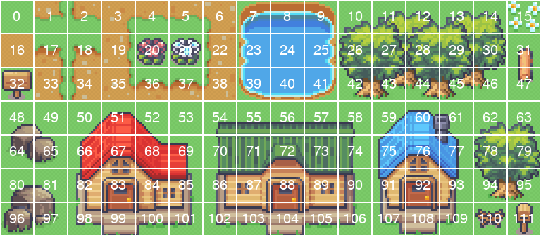
Then for each cell in fixed grid we specify which tile is placed there:

Grid with numbers on a black background, the number is the index of the tile that should be placed there

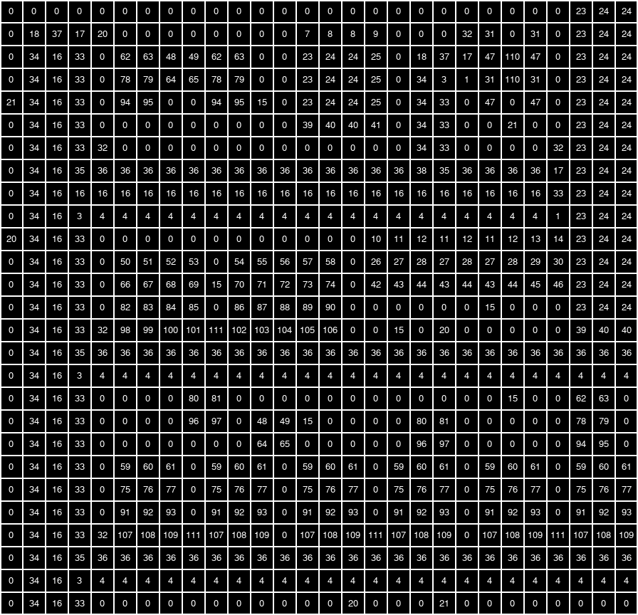
This will produce a map that looks like this:

Final tilemap result when tiles from tileset are filled into the grid using the provided index numbers

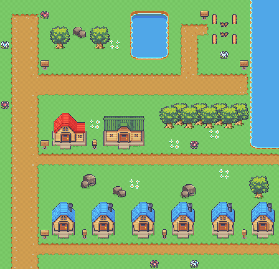
I wrote a small python program that takes a tileset image and a tilemap defined using CSV. It outputs a couple of C headers one gives the tileset data the other gives the tilemap data. It can also draw a preview image of the whole map. It can be found on github. The example tilemap above will be my demo map.

Drawing the tilemap is straight forward. First we define a structure to hold our tilemap data. Note it includes scroll_x and scroll_y fields. Our tilemap will be bigger than a single screen so we want to be able to move it around.

 1
 2
 3
 4
 5
 6
 7
 8
 9
10
11
12
13
14
15
16
typedef struct {
    // Width and height in tiles
    int width;
    int height;

    // Pointer to tile data. Each uint16_t specifies which tile from the tileset should be
    // displayed. Storage is row major order, so consecutive elements of a row of tiles are next to
    // one another.
    uint16_t* tiles;
    // Tileset data in RGB555 format
    uint16_t* tileset;

    // X and Y scroll in pixels for the tilemap
    int y_scroll;
    int x_scroll;
} tilemap_info_t;

Then we need a function to draw a tilemap to a line. This is simpler than sprite drawing as everything is arranged to a fixed grid and there’s no overlapping, priority order or transparency to deal with. Scrolling adds some slight complexity as you have to deal with partial tiles at the beginning and end of the line.

 1
 2
 3
 4
 5
 6
 7
 8
 9
10
11
12
13
14
15
16
17
18
19
20
21
22
23
24
25
26
27
28
29
30
31
32
33
34
35
36
37
38
39
40
41
42
43
44
45
46
47
48
49
50
51
52
53
54
55
56
57
58
59
// Return a pointer to a row of tiles from a tilemap. Line is specified in terms of tiles.
inline uint16_t* get_tilemap_line(int line, tilemap_info_t tilemap) {
    return tilemap.tiles + line * tilemap.width;
}

// Return a pointer to a row of pixels from a tile in a tileset
inline uint16_t* get_tile_line(uint16_t tile_num, int tile_y, uint16_t* tileset) {
    return tileset + tile_num * TILE_WIDTH * TILE_HEIGHT + tile_y * TILE_WIDTH;
}

// Given a scanline Y, draw the relevant pixels from the tilemap into the scanline buffer
void draw_tilemap_line(uint16_t line_y, tilemap_info_t tilemap, uint16_t* line_buffer) {
    // Translate from screen pixel coordinates to tile pixel coordinates using the scroll
    int layer_y = line_y + tilemap.y_scroll;
    int layer_x = tilemap.x_scroll;

    // Determine the tilemap Y of the line
    int tilemap_y = layer_y / TILE_HEIGHT;
    // Determine the pixel Y of the line within a tile
    int tile_y = layer_y % TILE_HEIGHT;

    // Determine the tilemap X of the leftmost pixel
    int tilemap_x = layer_x / TILE_WIDTH;
    // Determine the pixel X of the leftmost pixel within the first tile
    int first_tile_x = layer_x % TILE_HEIGHT;

    // Due to scroll the first and last tiles in the screen may only be partially displayed.
    // Determine with width of the first and last tiles
    int first_tile_visible_width = TILE_WIDTH - first_tile_x;
    int last_tile_visible_width = first_tile_x;

    // Obtain a pointer to the tilemap data for this line
    uint16_t* tilemap_line = get_tilemap_line(tilemap_y, tilemap) + tilemap_x;
    // Draw the first tile to the line, this is a special case as it may not be full width
    // Get a pointer to the pixels for the line in the first tile, offset by first_tile_x
    uint16_t* first_tile_line = get_tile_line(*tilemap_line, tile_y, tilemap.tileset) + first_tile_x;
    // Draw it to the buffer by copying the pixels
    memcpy(line_buffer, first_tile_line, first_tile_visible_width * 2);

    ++tilemap_line;
    line_buffer += first_tile_visible_width;

    // Draw the remaining tiles in the line
    for(int tile = 1;tile < TILES_PER_LINE; ++tile) {
        // Get a pointer to the pixels for the line in the tile
        uint16_t* tile_line = get_tile_line(*tilemap_line, tile_y, tilemap.tileset);
        // Draw it to the buffer by copying the pixels
        memcpy(line_buffer, tile_line, TILE_WIDTH * 2);
        line_buffer += TILE_WIDTH;
        ++tilemap_line;
    }

    // When the first tile is only a partial tile, so is the final tile. Draw that final partial 
    // tile here if required.
    if(first_tile_x != 0) {
        uint16_t* last_tile_line = get_tile_line(*tilemap_line, tile_y, tilemap.tileset);
        memcpy(line_buffer, last_tile_line, last_tile_visible_width * 2);
    }
}

To bring everything together I added scrolling to the sprite drawing code (see github to see the code), dropped the test pattern generation from the draw_line function and added the tile drawing leaving us with a very simple function:

1
2
3
4
5
void draw_line(int line_y, uint16_t* line_buffer) {
    // For each line first draw the tilemap then the sprites over the top
    draw_tilemap_line(line_y, test_tilemap, line_buffer);
    draw_sprites_line(line_y, line_buffer);
}

I also introduced an ‘entity’. Another structure that tracks a sprite along with some information to track how it should be moving and the animation to use. Here’s the entity structure, check out github to see the full code:

 1
 2
 3
 4
 5
 6
 7
 8
 9
10
11
12
13
14
15
16
17
18
19
20
21
22
23
24
25
26
27
28
29
30
31
// Each entity is either stationary or moving in a horizontal or verical direction
typedef enum {
    kMoveTypeNone,
    kMoveTypeHorizontal,
    kMoveTypeVertical,
} move_type_e;

// Entity data. Each entity has an associated sprite that it controls. The entity processing code
// move the sprite around (horizontally or vertically) playing the appropriate walk animation
typedef struct {
    // Index of the sprite associated with the entity
    int sprite_idx;

    // Index of the character the entity is using
    int character_idx;
    // Which frame within the current animation is being displayed (which animation can be
    // determined from the move_type and whether we're increasing or decreasing position)
    int anim_frame;

    // The entity either doesn't move at all or moves strictly horizontally or vertically. This
    // specifies the bounds for the movement (X coordinate bound for horizontal movement, Y
    // coordinate bound for vertical movement) and whether we're increasing or decreasing the
    // relevant coordinate for the movement.
    move_type_e move_type;
    int move_lower_bound;
    int move_upper_bound;
    bool move_increase;

    // When true entity should be processed
    bool enabled;
} entity_t;

Using this you can place a few animated entities around the map that move with appropriate walking animations. I also added some code to scroll the map and sprites together ‘bouncing’ when it hit the edge of a map by reversing the scroll direction. Here’s a video of the final result:

So what’s next? We can look at further layers, we could have multiple tilemap layers allowing transparency in some (so we can have tiles overlap sprites) or add a text layer (potentially implemented as another tilemap just with different tile sizes). Of course we will hit performance limits at some point (we only have so many CPU cycles to draw a scanline in) and start getting graphical artifacts. So first up we need to look into our current performance, see how many spare cycles we have to work with and see if there’s any way to improve our performance.

Whilst experimenting I found an interesting bug that looks like a performance problem. I recreated my initial sprite test (with the 128 sprites cycling through different animation frames) with a tilemap background. It worked fine still I started scrolling around as well at which point graphical artifacts started appearing.

After spending some time investigating I realised the graphical artifacts were only seen when the tilemap was scrolled in the X direction an odd number of pixels. Here’s a little video that demonstrates the bug. It scrolls one pixel right roughly twice per second. We see the artifacts come and go with every pixel step until we’ve got 8 or fewer sprites per line and suddenly everything works fine. A clear sign of a performance issue. For some reason a tilemap scrolled an odd number of pixels needs noticeably more cycles to draw than a tilemap scrolled an even number of pixels.

I have yet to look into the root cause of this. I suspect it’s something to do with aligned vs unaligned memory access. With 0 scroll pixel 0 and 1 of the first tile are copied to pixel 0 and 1 of the scanline buffer and can be done with a single aligned 32-bit copy. With a 1 scroll pixel 1 and 2 of the first tile (pixel 0 is off screen) are copied to pixel 0 and 1 of the scanline buffer. Either two 16-bit copies or one unaligned 32-bit copy. I’ll investigate in more detail in the next blog.