Playing with the Pico Part 3 - PWM Audio
I decided to experiment with audio on the pico next. The pico doesn’t directly give you a DAC (digital to analog converter) to produce an audio signal so you need extra circuitry to get one. There are of course many chips that can the job for you but there’s a simple way using PWM along with a capacitor and a resistor or two.
When driving LEDs with PWM, the inability of our eyes to see sufficiently rapid flickering means the fully on to fully off blurs into varying levels of brightness. We can do the exact same thing with audio where the PWM blurs into different voltage levels representing our audio signal. Directly driving a speaker or headphones with a PWM signal can work but I’m going to add an RC (resistor capacitor) filter to give a better audio signal.
Full code can be found on github
Building and testing the RC filter
I used the components I had to hand so choose a 68 Ω resistor and 0.1 μF capacitor, when connected in series these form a low pass filter blocking frequencies above 23.4 kHz, a bit above the range of human hearing. This is connected between a pico pin and ground with the output taken from the voltage across the capacitor.
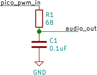
First of all I ran a program to iterate through 16 different PWM output levels, changing once per second going up then down. I placed a multimeter across the capacitor to check voltage levels were going up and down in the steps expected and they were.
|
|
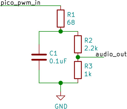
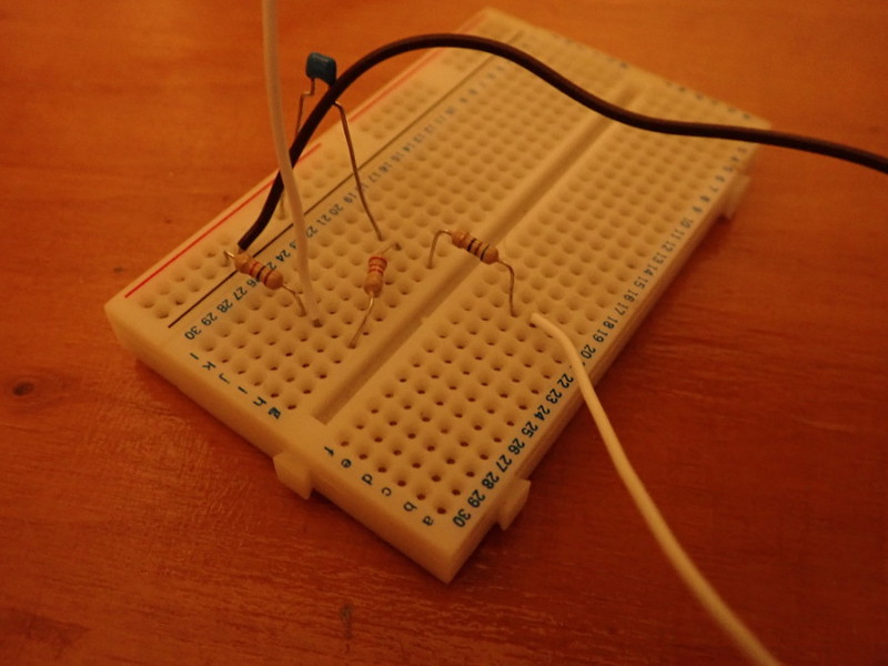
Next I wanted to bring this down to a line level voltage for an audio output, around 1V maximum. The easy way to do this is with a potential divider. I initially experimented with using a divider connected directly to the pin with the capacitor over the lower resistor. I wasn’t convinced this would work well, the step and down experiment from above didn’t work properly. I suspect this is because the lower resistor is discharging the capacitor whilst the upper resistor is charging it and you don’t reach the voltage level you want quickly. I could increase both resistances to minimise the discharge current but then the charge current would also be diminished. Instead I tried a separate divider wired across the capacitor using 2.2k and 1k resistors (see circuit and photo below). This looked to work with my multimeter test, voltage stepping up and down as expected topping out around 0.8v.
Check out section 3.4.1 of Hardware design with RP2040 for a better PWM audio circuit, including stereo
At this point it’d be useful to use an oscilloscope to take a look at what’s going on at a more detailed level, especially when I start trying to produce audio waveforms, unfortunately I don’t have one. However the Pico does have an onboard ADC (analog to digital converter) capable of 500 kSps (kilo samples per second). With my filter topping out at 23.4 kHz that should be more than enough samples to get decent audio waveforms. Accuracy will be nothing like a proper oscilloscope but it should do the trick for my purposes.
To get a good trace we want accurate sample times, luckily the Pico ADC provides this for us with a free running mode where it samples every N cycles and writes samples into a FIFO queue. You can use the DMA to read these out and write into memory. This will give you accurate sampling at a controllable rate with very little CPU involvement.
To get this setup we’ll need a DMA channel configured to read from the ADC FIFO address and write to a memory buffer, with the DMA DREQ set to the ADC so it reads every time the ADC produces a new sample. Sample rate needs careful consideration, whilst higher is better we’ll fill up memory quickly. For my initial test I’ll use 25 kSps. Samples are 2 bytes each (12-bit resolution) so we’ll need around 50 kB of buffer space to store 1 second. The sample rate is too low if we’re looking at 23.4 kHz signals but I won’t get anywhere near that for my initial testing and a longer total sample period may be useful.
Here’s the code to set that all up:
|
|
Initially I used the same code for my multimeter test with quicker level changes, it would step up and down 16 levels in a bit under a second. I also changed the max counter value in the PWM from 65535 to 254. With the larger counter value you get less than 2'000 PWM cycles per second. Clearly we need more for PWM audio, a max count of 254 gives almost 500'000 PWM cycles per second along with 256 possible levels (255 full on, 0 full off and 1 - 254 representing varying mixtures of on and off).
Measuring the output of the stepping up and down test via the ADC gives a graph like this (I dumped the sample buffer over serial when the capture finished which could be logged and opened directly as a .csv).
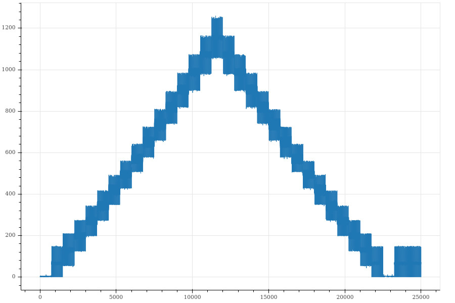
You can clearly see the steps though it looks pretty noisy, here’s a zoom of one of the steps. Lots of large spikes.
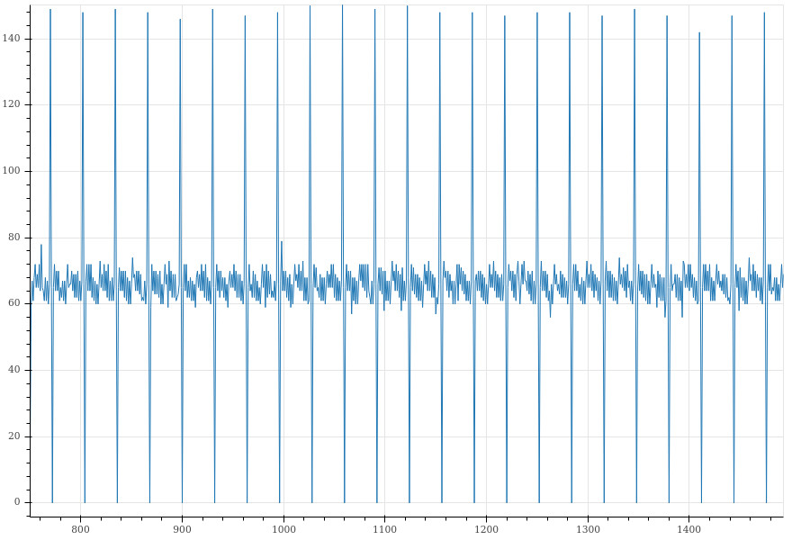
I decided not to worry too much about this, filtered PWM is never going to give you a perfect level, the measurement via the ADC may be introducing some noise or artifacts plus the RC low-pass filter is meant to deal with varying voltage, not DC levels, we may get a nicer result with a proper audio waveform, so let’s check that out next.
Trying an audio waveform
44.1 kHz is a common sampling rate for high quality audio, we are unlikely to get high quality audio out of this so let’s go for 22 kHz to keep memory requirements down. We want to keep the PWM max count at 254 so there’s only 1 byte per sample, so we’ll use a PWM clock divider of 22.1 to give us 22'000 PWM cycles per second at Pico’s default 125 MHz clock.
We need a way to feed the audio data to the PWM channel, DMA can be used. Like Part 2 we want a continuous loop of some sequence, but this time we’ve only got one PWM channel to drive. A single DMA channel setup to copy from the audio buffer to the PWM will do the trick, with an interrupt when it’s done which will set it off again.
Sadly using DMA gives us an issue with 8-bit samples. The DMA can copy 8 bits at a time but when writing to a PWM register, which is 32-bits, this 8-bits gets replicated across all 4 bytes for the write, which isn’t what we want. To fix this our audio buffer will be 16-bit samples though with a max value of 255 (if we used all 16 bits we don’t get a high enough PWM frequency to produce audio). This wastes memory but will do for testing purposes.
Here’s the code:
|
|
|
|
For our test audio sample we’ll use a 440 Hz tone. Running this results in the follow ADC capture. Not the smoothest waveform but recognisable at least. I tried taking out the potential divider to see if it made a difference but it didn’t have a noticeable effect.
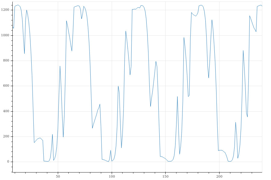
What could we do to improve it? Currently there’s one audio sample per PWM cycle, would changing this ratio help? I decided to repeat each sample 4 times in the audio buffer and change the PWM clock divider to 1/4 of what it was (from 22.1 to 5.5), things are much improved if still a bit spiky.
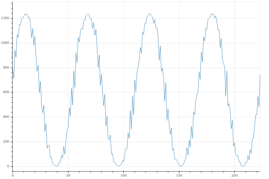
Measuring one peak to peak distance is 56 samples, the DAC runs at a fixed 48 MHz clock and was setup to sample once every 1'920 clocks. This gives a frequency of 446 Hz for the tone (48'000'000 / 1920 / 56), close enough to the intended 440 Hz, especially as 440 Hz doesn’t fit into a whole number of ADC samples.
Combined with the need for 16-bits per sample we’re now using 8x the memory for the audio buffer compared to the memory required for the raw audio data. So for now we’ll forget about using DMA and do everything with the CPU and a PWM interrupt. When the PWM cycle is complete the interrupt fires, the CPU determines the next audio sample and writes it out to the PWM slice register. The interrupt handler can do the 8-bit -> 32-bit expansion required as well as the sample repetition without wasting memory.
|
|
As I still had some LEDs hooked up from Part 2 and all audio samples were handled in software I added some code to the PWM interrupt handler to make the LEDs a primitive VU meter.
|
|
Finally I didn’t have a audio jack to hand I could wire into my circuity. I did have a jack to jack audio cable though, so I just wrapped some wire tightly around one end, which plugged into the filtered PWM output and ground. The other end connected to a small powered speaker that had a line-in input.
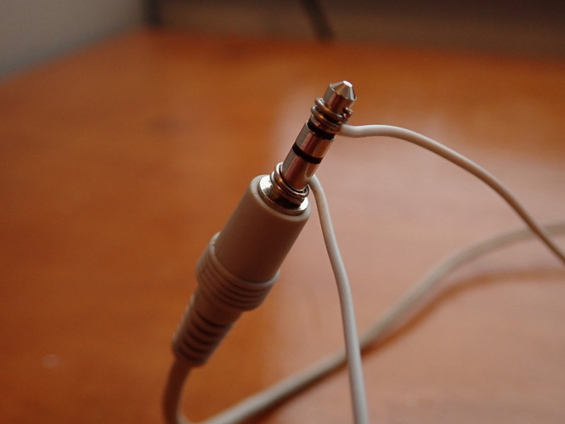
Here’s a video of the final result playing a short music clip 1, you can see the external microphone I used to record the audio. I was surprised at the quality, you can just about hear some background hiss and it may not work so well with other audio but for PWM driving a capacitor and a few resistors via breadboard and signal wire it does a very good job!
I was interested to see how much difference repeating the samples made. I tried again with the original PWM clock divider giving us one PWM cycle per audio sample at 22 KHz and it still worked well. I think I could discern a difference (in person, it wasn’t noticeable on a recorded video) but it wasn’t a major dip in quality. Given the 440 Hz tone definitely benefited from the sample repeat I think it’s worth keeping, 4x should be sufficient. I did try 8x as well but couldn’t really hear a difference between it and 4x.
Using DMA to stream audio
As discussed above whilst we can use DMA to stream our audio data directly, there’s a couple of issues:
- Reads and writes have to be 16-bit, so we have to use 16-bit per sample, padding out our 8-bit samples with zeros
- To repeat samples we just repeat them in the buffer
This makes the buffer we’d use for DMA 8x the size of the raw audio (4x sample repeat and 2x 8 - 16 bit). Can we do better? Of course!
As in Part 2 if we get creative with multiple DMA channels using DREQs, chaining and triggering we can produce some complex behaviours. By using three channels we can stream directly:
-
The stream channel, it copies 1 byte at a time from the audio buffer to a fixed location. It’s configured to transfer one byte and stop.
-
The PWM channel, it copies 4 bytes at a time from the fixed location to the PWM slice on a PWM DREQ and it’s configured to transfer 4 times. It’s chained to the stream channel so when it’s done the next audio sample is copied to the fixed location.
-
The trigger channel, it keeps everything running. It triggers the PWM channel by writing to one of its trigger registers. It’s also connected to the PWM DREQ and configured to transfer the total number of samples multiplied by 4.
The interaction between the PWM channel and the stream channel does an 8 bit to 32 bit expansion for us. We need to ensure the fixed location is initialised with 0, the stream channel copies 1 byte in and the PWM channel 4 bytes out, one is our sample the other will be 0. The PWM channel does the sample repetition by copying the same sample value to the PWM 4 times.
The trigger channel kicks the PWM channel into action but will do further transfers whilst the PWM channel is doing the sample repetitions, these are simply ignored as the PWM channel is active. If we had a DREQ that fires 1 every 4 PWM cycles we’d use that, but we don’t 2.
Here’s the code that sets it all up, there’s an interrupt setup to fire when the trigger channel is done which resets the cycle and starts it off again.
|
|
|
|
We could also look at using PIO here, something to look at another time.
-
Clip taken from audio sample ‘Angus Lejeune Theme’ by maxcruger at freesound licensed under CC BY 3.0 ↩︎
-
We do have things called pacing timers, which will cause a DMA transfer every N cycles, potentially they could be used instead of the PWM DREQ here so the trigger channel would only transfer once per repetition cycle. There may be issues with making it all sync up so I went for the DREQ method for simplicity. ↩︎