Playing with the Pico Part 2 - Driving PWM with DMA
One of the things that interested me on the Pico was the DMA engine. For those who don’t know DMA stands for Direct Memory Access. It’s something which can do memory copies for you. A basic DMA engine takes a source address, a destination address and a length and copies data from source to destination. This frees up the CPU from memory copy loops allowing it to do other things. They’re vital parts of many computer systems and have been for decades, so what’s so interesting about the Pico’s DMA?
The Pico’s DMA has several extra features. It has 12 channels, allowing 12 copy operations at once. It allows chaining where one channel finishing triggers another. The DMA can control peripherals too, as their registers look like any other memory to the DMA, so one DMA channel can control another. Combined with chaining this allows some interesting possibilities.
I decided to build a little demo where RGB LEDs were driven by the Pico’s PWM channels. I’d have a predefined colour sequence for each of the LEDs to follow and I’d use the DMA to do as much of work as possible, reading the colour sequence from memory and sending it straight to the PWM channels without CPU involvement.
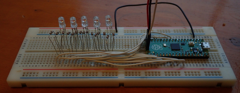
I put together a setup on a breadboard with 5 RGB LEDs using 15 of the 16 PWM channels. Beware that the RP2040 has a max IO draw of 50 mA, which I may be exceeding with my test setup, choose your resistors with care if you try this yourself.
Controlling PWM with DMA
Full code can be found on github
Streaming values to a single PWM channel using DMA is straight-forward. Point the read address at the values, point the write address at the PWM channel, have it only auto increment the read address and set it going.
The DMA will dutifully stream your desired values to the PWM channel, but there’s a problem, timing. The DMA will write the values across as quickly as it can. Depending on the PWM cycle time you may just see the start and end value from your list actually effect the PWM output.
The Pico provides a solution in the form of DREQs. A DREQ tells a DMA channel when to transfer data. The PWM provides a DREQ at the end of its cycle, which solves our timing problem.
My first step to check I’d got the basics right was to fade an LED up by putting increasing values from 0 to 2^16 - 1 into a buffer. Using a DMA channel to stream these out to a PWM channel, copying a new value on each PWM DREQ. The core of the code is below along with a highly exciting video if it in action.
|
|
Multiple PWM channels with three DMA channels
This was a good start, we can fill a buffer with various brightness values for an LED, connect the LED to a PWM channel and leave the DMA to do the rest. The issue is you need one DMA channel per PWM slice (two channels per slice). So to drive all 16 PWM channels you have to use 8 DMA channels in parallel. Can we do better?
We can, thanks to chaining and DMA trigger registers. We’ll use two DMA channels, one, the PWM DMA channel, copies values from the buffer to the PWM slices, The other, the control DMA channel, will tell the PWM DMA channel where to write next. The PWM DMA channel is chained to the control DMA channel so they ping-pong off each other. The PWM DMA channel copies a value to a PWM slice, then chains to the control DMA channel. This writes a new write address to a PWM DMA channel trigger register which sets the PWM DMA channel off again.
Here’s the code that sets it all up, pwm_data is a pre-computed set of values
for the PWM channels. The DMA channels will iterate through the data, copying
values to each of the PWM slices in turn. There’s 2 PWM channels per slice so 8
values gives us 16 PWM settings representing a single point in the LED colour
cycle we want.
|
|
The control DMA channel reads from pwm_dma_list, which contains the addresses
of the PWM slice registers. These get written into the PWM DMA channel’s write
address register. One of these writes triggers the PWM DMA channel to do a
transfer, reading an element of pwm_data out to a PWM slice. After the
transfer is chains back to the control DMA channel which writes the next PWM
slice register address and the everything repeats. The final element of
pwm_dma_list is 0 which doesn’t trigger anything, stopping the process.
I tested this by starting the control DMA channel once to see if I’d got things setup correctly by seeing all the LEDs lit up with the expected colours.
In order to update all of the channels every time we reach the end of a PWM cycle we need something extra. We could just sit in a tight loop delaying for an appropriate time triggering the control channel each time but I wanted to do as much as possible without using the CPU.
The answer is a third DMA channel, the trigger DMA channel, which writes to the control DMA channel read address trigger starting a cycle of PWM writes. You can link this to the DREQ of one of the PWM channels so it triggers every time the PWM cycle ends.
The data in pwm_data has 512 values for each PWM slice (512 x 8 slices = 4096
values all in all), so we tell the trigger DMA channel to do 512 transfers which
will go through the full set of PWM data.
The code to setup the trigger channel is below:
|
|
To get a continuous cycle we need to loop starting the trigger DMA channel and
setting the PWM DMA channel read address to the beginning of the pwm_data data
buffer. For testing purposes our loop will do this then wait a few seconds for
the cycle to run before repeating which the following code accomplishes:
|
|
I setup a test pattern in pwm_data that fades some colours in and out This
allowed me to check everything was working as it should, here’s another slightly
more exciting video:
Repeating the colour loop with interrupts
Can we get rid of the busy loop? Interrupts are the answer. The DMA can raise an interrupt when the trigger DMA channel is done, set it going again in the interrupt handler and we’ll have an uninterrupted loop of the colour cycle with the CPU only having to deal with the occasional interrupt to keep it going.
Here’s the interrupt handler and the setup code, note the line at the end of
handler writing to dma_hw->ints0, this clears the interrupt from the DMA.
Without it the CPU loops forever handling the same interrupt again and again,
guess what I missed off the first time I tried this?
|
|
|
|
So we’re done? Not quite here’s another video
We get a couple of repetitions of the test sequence then something goes wrong. What’s happening? When we trigged the cycle in a loop with a time delay everything was fine, the interrupt is doing the same thing but with different timing. It looks like some kind of race condition, two things trying to read or write the same value where the order they do it in changes the behaviour.
I put a busy_wait_us at the beginning of the interrupt to it delay a little.
Normally this is a very bad idea (you want interrupts to be quick not sitting in
time delay loops) but it’s a useful debugging technique.
Lo and behold this fixes things and we get continuous repetitions of the test sequence.
What’s the race condition we’re seeing? It’s to do with the read address of the
PWM data channel. When the trigger DMA channel sends its interrupt the other
channels are still running. If we get to the interrupt code quickly enough they
won’t be done yet. The interrupt handler then prematurely resets the PWM DMA
channel read address and it reads the first few values as if they were the last
few values. Then we start again a few elements into pwm_data. This gives the
weird result from the video.
To fix it we want to avoid updating the PWM DMA channel read address until we
know the sequence is done. The key to fixing it is the 0 value at the end of
pwm_dma_list. When this is written to the PWM DMA write address register the
sequence is done.
The easy fix is to use a polling loop checking the PWM DMA write address waiting until it’s 0. Ordinarily a polling loop in an interrupt is a very bad idea but in this case I think it’s reasonable. The control and PWM DMA channels don’t have much work to do and will finish rapidly so the loop won’t wait for long. Here’s the final interrupt handler:
|
|
With that the race condition is fixed and we can run our full sequence over and over with the CPU only having to execute an occasional interrupt handler. I made a more interesting colour sequences with some rainbow colours, here’s a video of the final result
Another Race Condition Fix
I added counters to the DMA interrupt handler to see how much time it delayed waiting for the PWM DMA to finish. The polling looping did two iterations at most so it seems reasonable to keep in the interrupt handler. Though what if were longer, is there another way to fix the race condition?
One solution is a second DMA interrupt. You can configure a channel to interrupt in one of two scenarios
- It’s finished all its transfers
- Something writes a 0 value to one of its trigger registers
Scenario 2 is handy where you have the chaining setup we have with the PWM and control DMA channels. Scenario 1 is no good as you’d get an interrupt every time they ping-pong back and forth, scenario 2 gives you an interrupt when we’ve reached the end of the chaining.
We can use the 0 value interrupt to know when the PWM DMA channel is done, the issue is if we enable it from the start we’ll get an interrupt at every new set of PWM values rather than one once we’ve had the whole sequence.
To avoid this we enable the 0 value interrupt when we’re in the interrupt handling the end of the DMA trigger channel. Then we start the whole sequence again when the 0 value interrupt occurs.
The code to deal with this is as follows, note we have to be careful we don’t miss the NULL value being written and end up waiting forever for the interrupt.
|
|
|
|
This is a more complex solution and introduces new potential bugs like the missed wake-up. I think the first solution is a better choice for this application. For another, where the polling loop may be waiting a while the second could be better.
Conclusion
You might be wondering why bother with all this complexity for streaming a few values to PWM channels (plus the memory for the pre-computed PWM values)? You’d be right to do so, I set out to push the DMA as much as possible to see what I could do, not build the most practical LED PWM animation code, I enjoyed doing it but likely wouldn’t use this in a real application. For other applications these techniques will be more useful, e.g. the Pico can drive a video interface, something I have yet to try but there will be lots of data to move around with precise timings and you want to save CPU time for other things.